


Preparing the Action
Since the miniature Martini breach block’s face is not perpendicular to the axis of striker travel conversion of a rimfire block to centerfire uses two dial-in references.
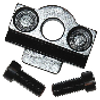
The dial-in with a snug fitting gauge pin in the block striker bore will be used for three operations: 1) the EDM setup to remove the striker nut retaining screw that was broken off in the hole; 2) tapping the original firing pin hole; and; 3) drilling the new firing pin hole. This is what the setup looks like.

The rimfire breach block that is being converted to centerfire was secured in a tool maker’s vise and was dialed in on a surface plate as shown above. The setup was moved to the mill and a 4-40 tap was used to thread the existing rimfire firing pin hole to the full depth of the hole. A 4-40 bead blasted screw was then screwed into this hole leaving the screw proud of the breach face. The circumference of the protruding screw was TIG welded to the breach face.

The block was then set up again in the tool maker’s vise and the block face dialed in. The setup was then taken to the surface grinder. The protruding part of the screw, as well as the bead of weld surrounding it, were brought a level with the face.

Preparatory to locating the new firing pin the existing firing pin was ground from the striker nearly to the striker flange. Again the block was dialed in on the surface plate with the gauge pin in the striker bore and with the vise turned onto its side the new firing pin hole could now be drilled. The new firing pin location is off center of the axis of the striker but this setup would ensure that the new firing pin would be parallel to the striker axis and would not bind as it travels longitudinally back and forth. The center of the barrel axis had been previously established with the block installed in the action and this center was marked on the breach face. The setup was moved to the mill and with the striker installed in the block under full tension of the striker spring a 1/16” hole was drilled through the breach face and into the striker flange. This spotted hole on the striker flange would then be center of the new firing pin location.
A section of 1/16″ O-1 drill rod was soldered into the striker and after the parts of the breach block unit were reassembled the firing pin was shortened and then rounded to give a pin protrusion of .055”.

The last work that needed to be done on this block was a removal of the striker nut retain screw. The block came to me with this screw broken off and I drilled the screw out as best as I could. It is something like a 5-56 screw and after drilling the screw with a still smaller twist drill there were thread remnants that I thought I could remove with the tap. I broke the tap off and Morris used the EDM to remove the tap. The threads were then carefully cleaned up and the new screw fitted.

Preparing the Barrels
By now we had four ovate barrels that needed fitted to the action. The preparation consisted of work that I am simply not capable of doing even with the excellent machines made available to me. This was Morris’ show and I gratefully moved aside.
The first problem was that the exterior of each barrel was rough. Two of the barrels had not been rough turned on the exterior and these not only had significant rust on the exteriors but the bores were noticeably off center in the full round blanks. The other two barrels also had bores that were off center but not to the degree of the other two. All had bores that were remarkable straight so work on them proceeded.
Morris set the barrels up on the lathe on centers and carefully trued a section on each end of the barrel to be concentric with the bore. Very precise tolerances were maintained for this operation. As each barrel was held between centers very light skim cuts were performed on each barrel until the outsides were trued to the axis of the bore.

Using the trued section on the breach end of each barrel as a reference point the overall length of the barrel set was established at 26” and each was precisely brought to this length.
Morris’ description of process: “After the shortest barrel had been faced on and had centers cut on both ends I stood it on end on the surface plate. The rest of the barrels were faced on one end and had center cut I stood them next to the finished barrel and used a depth mic to determine the amount to shorten the remaining barrels. This resulted all barrels being within .005 of the same length.”
Each barrel was crowned at the breach and the muzzle.
Morris’ description of process: “Total run out with the barrels chucked in the 4 jaw chuck was .0002/ the ends of the blank were faced and a 60 degree center was cut in the end using a boring tool feeding the tool from the bore out to draw burrs out that result from turning. The barrels were next placed between centers with tailstock pressure only and a 2 inch section was turned concentric with the bore. after this step it was possible chuck one end of the barrel in the 4 jaw chuck and indicate both ends of the barrel. The center was then used to support the barrel and the entire outside was turned concentric with the bore.”

The action barrel tenon was cut on each barrel and this tenon was threaded using a 55° tool. The leading edge of this tool was rounded manually to produce the appropriate Whitworth thread cut in the action.
Morris’ description of the process: “A 55° threading tool was ground on the surface grinder that allowed the thread to be machined to the shoulder eliminating the relief cut and allowing the threads to be turned to the shoulder adding strength to this critical area.”
Morris made a tool fixture for cutting threading tools using the surface grinder. This is a very precise fixture that gives extraordinary tools. Because this one is set up for cutting a 60-degree angle a sine plate needed to be used to reduce it to the required 55°.

Each barrel was then threaded to give a consistent snug turn-in to the action face. With this takedown system using four barrels, it is important to have precise tolerances from barrel to barrel.

Finally, each barrel was then chambered using a floating reamer holder in the tailstock.
Morris’ description of the process: “The chambers were cut to a feel on the go gauge + .001 shim stock. The chamber reamers were removed as soon a the chips were showing in the flutes dry. The reamer was then removed, cleaned and thoroughly oiled. several dry patches were run through the bore. The reamer and copious amounts of oil were reinserted and the entire process restarted.”

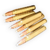
Each barrel was screwed into the receiver with its appropriate breach block installed and firing tests were conducted to ensure primer ignition. Because the head diameters of the .22 LR and the .17 HMR are slightly different I had some concern about whether the rimfire block firing location set up for the .22 LR would detonate both the .22 LR and the .17 HMR cartridges. Both tests resulted in detonation and the conclusion is that no adjustment to the location of the rimfire firing pin is needed.


Using the EDM to cut the takedown screw groove on each barrel’s thread bottom will be covered next.


